
Featured
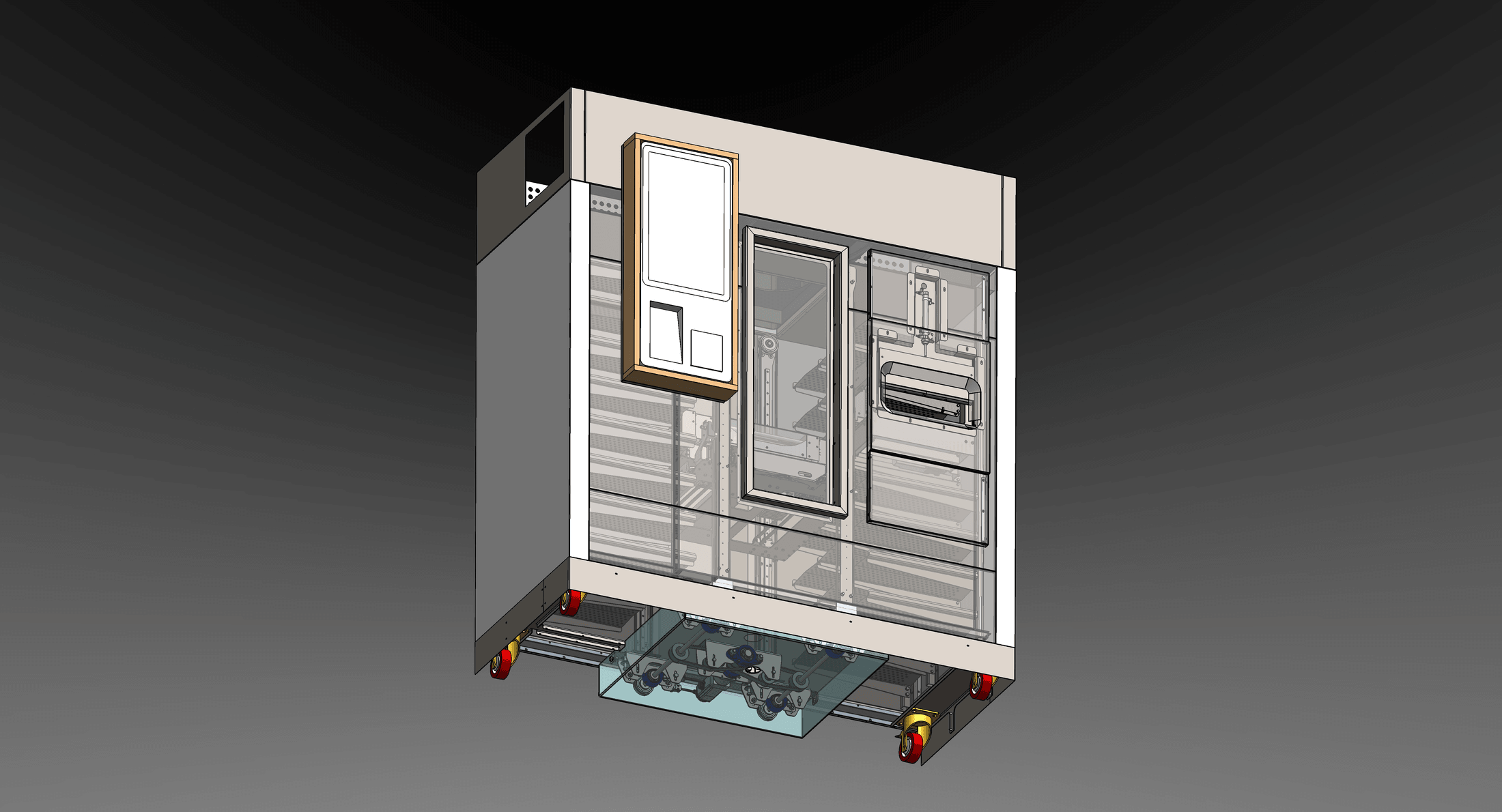
Refrigerated Automated Storage & Dispensing Robot
Cartesian style robot, with dynamic storage arrangements and patented product manipulation
- Sector
- Automation
- Years
- 2023–2025
- Engagement
- In-house
- Role
- Lead Engineer & Primary Mechanical Design Engineer
- Status
- Prototype validated; four pre-production units built
- Client
- Future Robotics
Patent PCT/EP2025/055523; A Robotic Food Vending System
SolidWorks · Sheet metal design · Manufacturing drawing · Siemens PLC (basic troubleshooting and test) · Machine building and testing · R&D · Supplier Liaison · Management & Coordination
Problem
Conventional refrigerated vending fixes slot size, so unit capacity is set by the largest product it must hold. The commercial driver here was capacity, specifically for meal sized boxes across roughly three size classes. The brief was a machine where any slot accepts any product within a defined envelope, packing arrangements dynamically, handled by a single gripper head rather than size specific mechanisms.
Constraints
- External envelope fixed by the top mounted refrigeration housing; not alterable as the design evolved
- Internal shelf and cell layouts fixed early in the project
- Product envelope 170 × 90 × 400 mm (W×H×D)
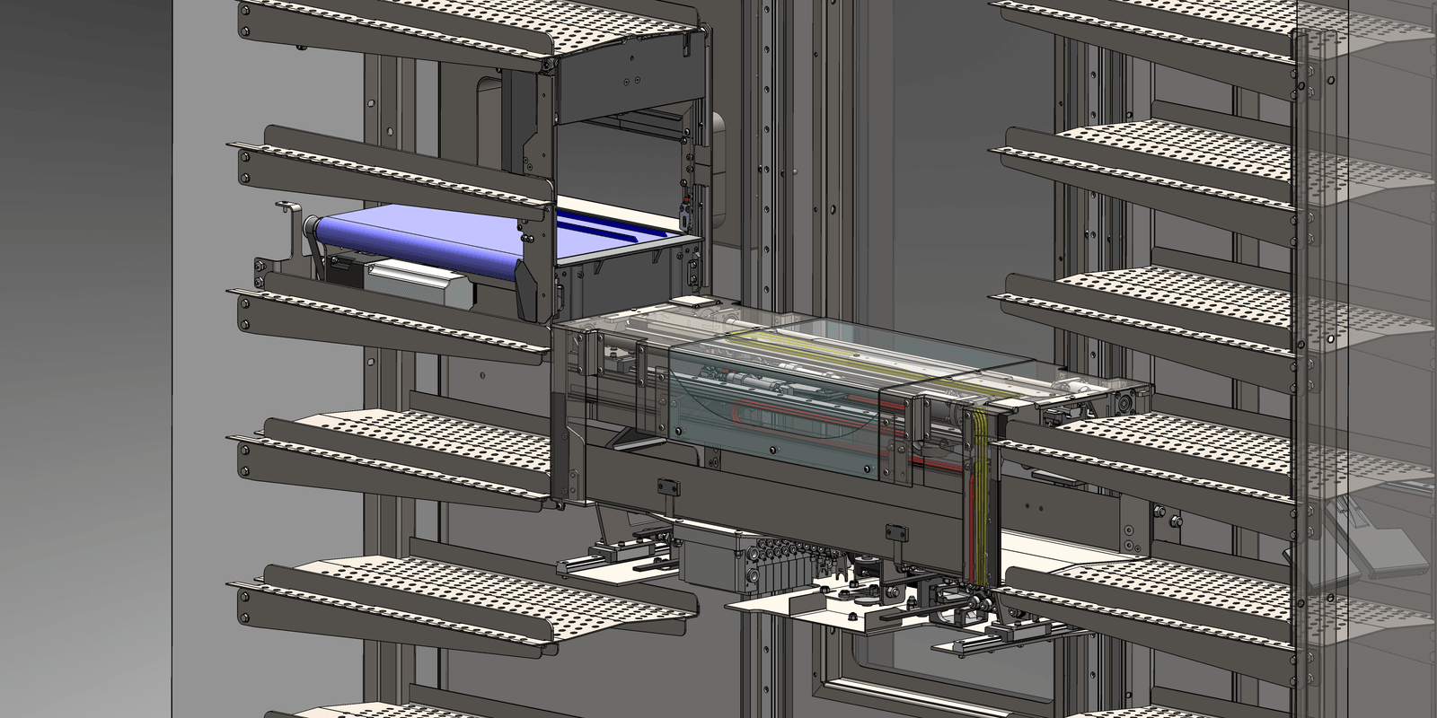
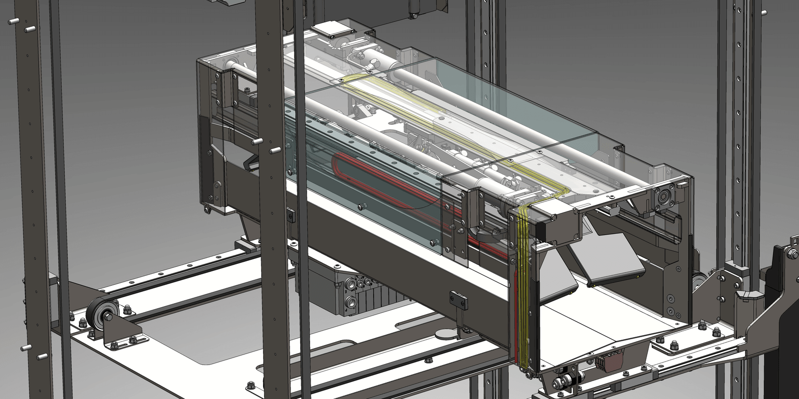
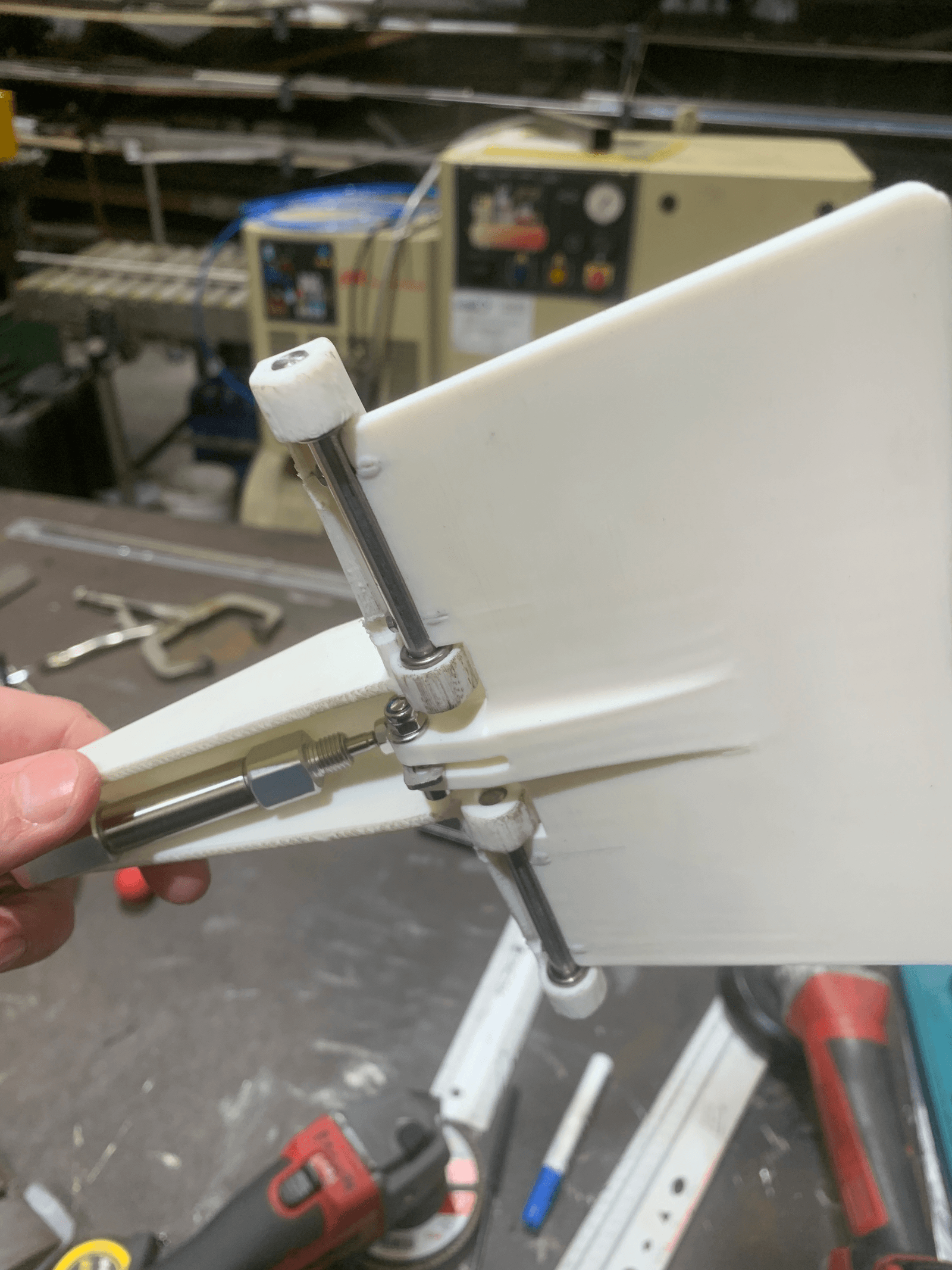
- Single two sided gripper head handling every size class with one operation
- Pre-production redesign had to retain prototype mounting points, cutouts and interface geometry
- Full load from empty in under 20 minutes; the primary driver of ballscrew lead and motor selection
- Customer dispense of a complete 2 to 3 item order in under 60 seconds
- Products pre-sealed, so hygiene scope was routine internal cleaning; all shelves stainless steel and removable for washdown
Approach
- Owned all mechanical architecture: mechanisms, ergonomics, safety, maintenance access, cable routing, material selection
- Reversed the packaging strategy for V1.1; auxiliary components placed in the model before carriage chassis geometry was fixed, where the prototype had let structure drive component placement
- Designed as a hierarchy of independent sub-assemblies, allowing parallel design, build and rework
- Modelled all electrical and pneumatic components inside the mechanical assemblies to verify clearance and routing before build
- Sequenced sub-assembly design by estimated supplier lead time, releasing long lead items first and replanning continuously around delays, test results and revisions
Gallery
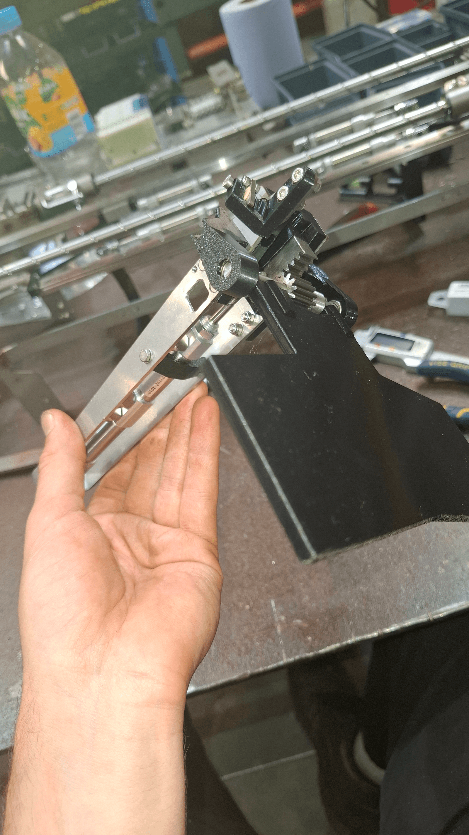
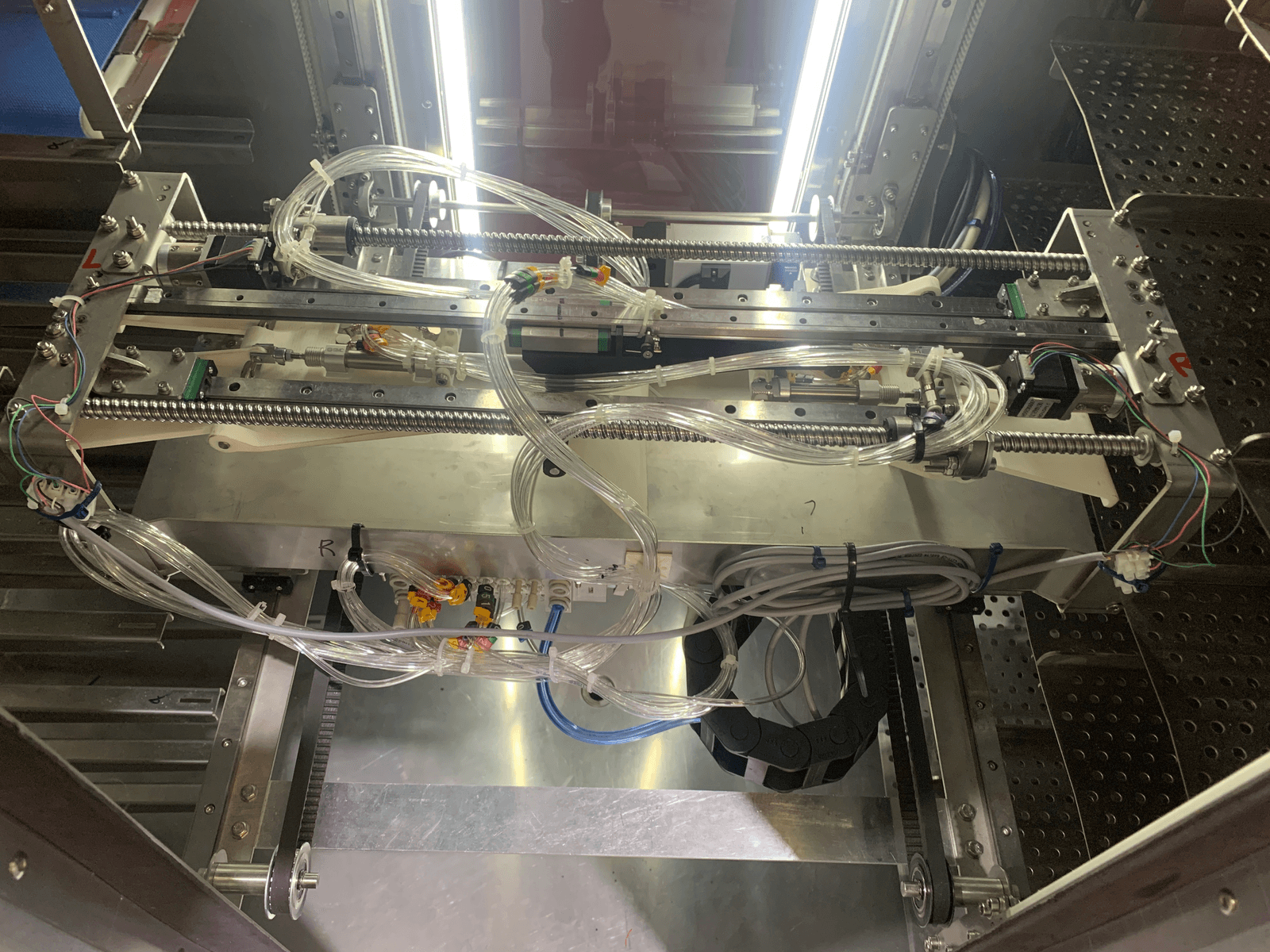
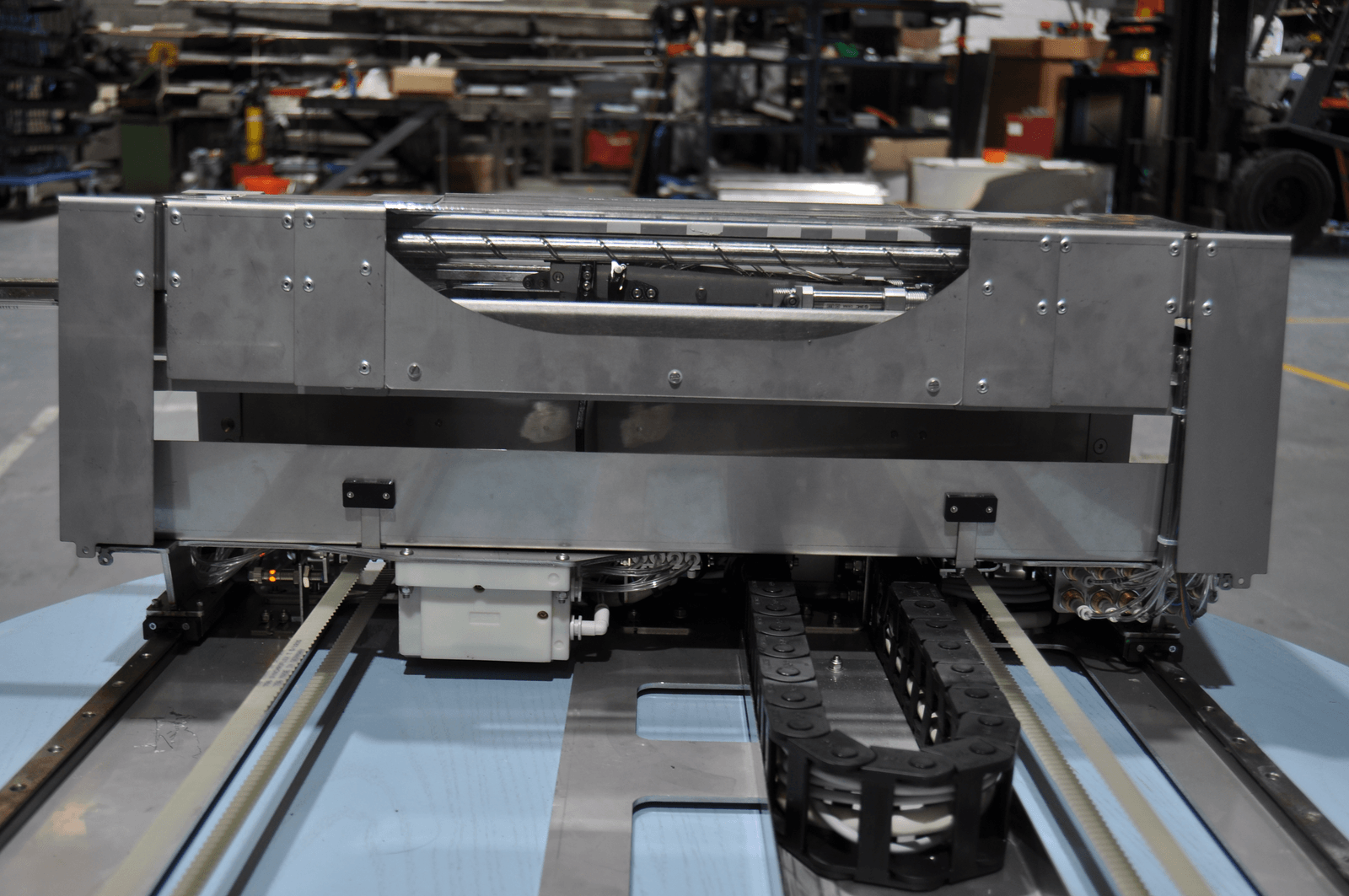
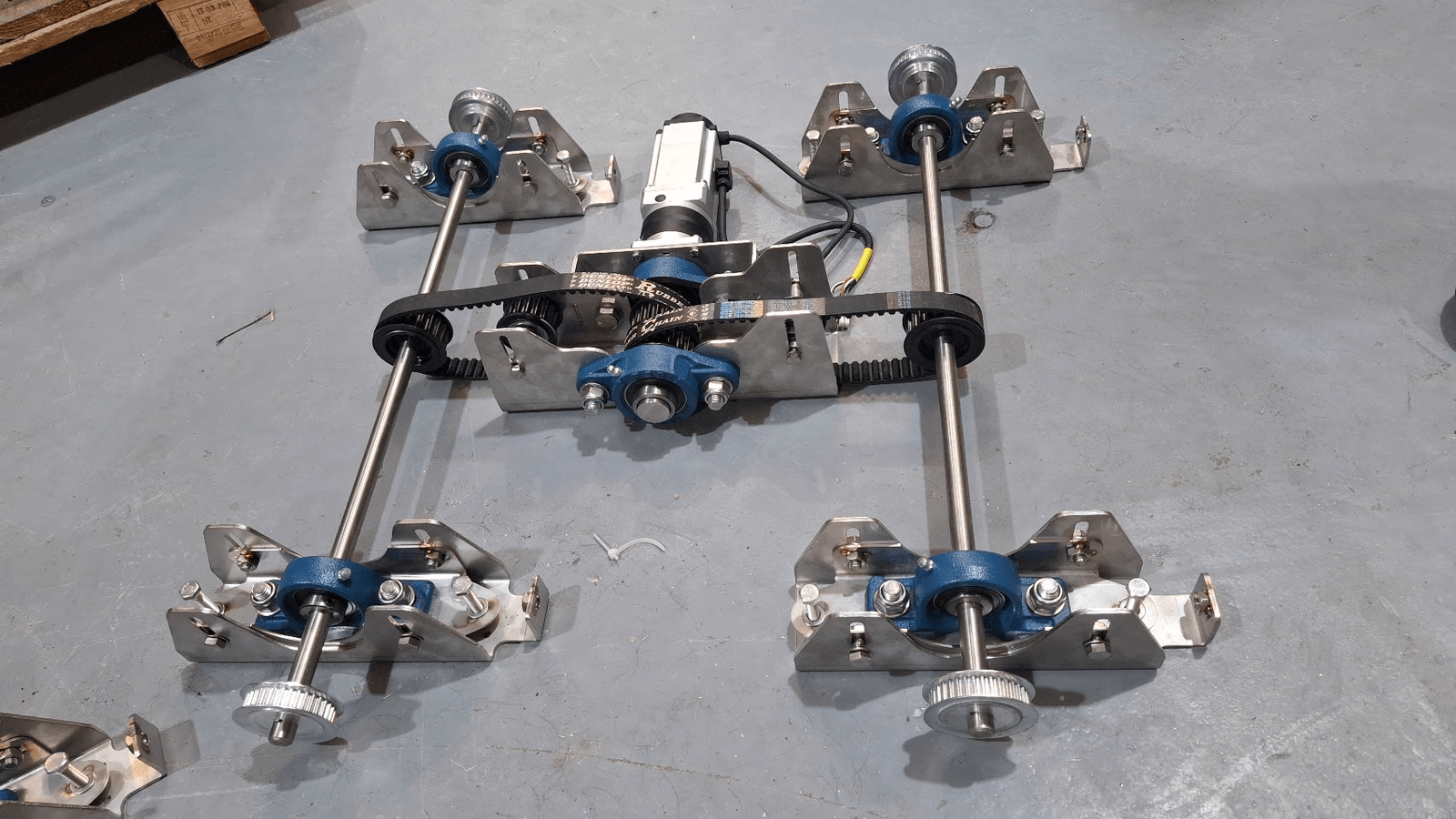
Outcome
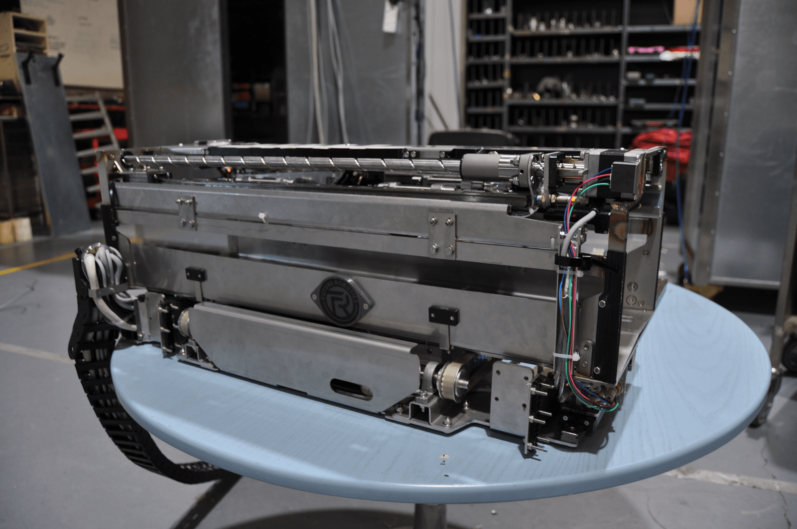
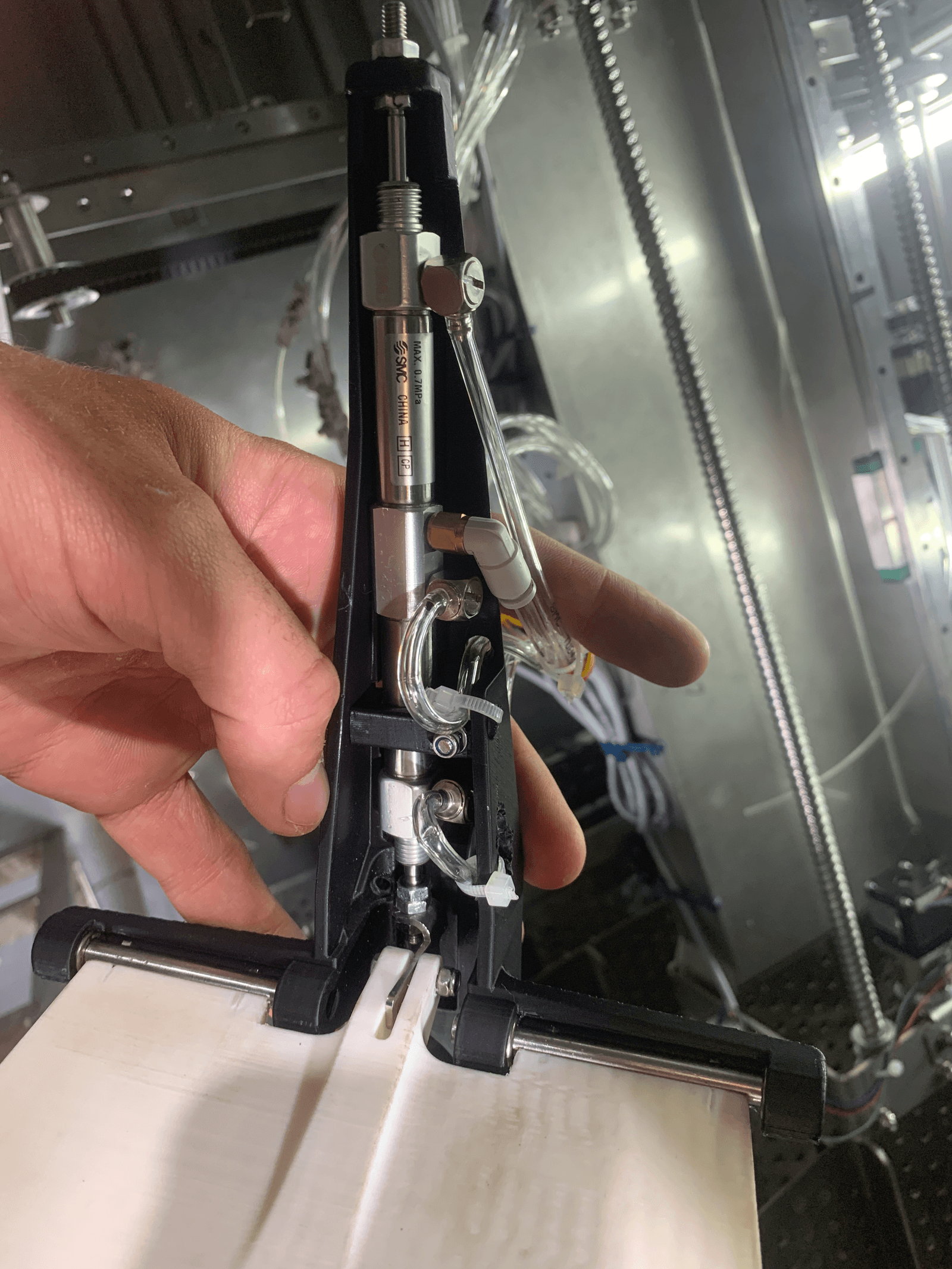
The prototype validated the manipulation concept. Four pre-production units followed, with improved robustness and adjustability, faster assembly, and pneumatic routing concealed within the head envelope. Product height capacity rose from 75 mm to 90 mm and ballscrew extension time fell from roughly 30 seconds to 5. The prototype took four months to build; the four pre-production units took three, assembled single-handed. Development ended when the company ceased trading.
Testimonial
“He has a very inventive mind and is always able to find a solution to any problem that comes his way.”
See full testimonial
Further detail
D1Z-axis actuation: prototype to pre-production
Three targets came out of prototype testing: speed, product height (75→90 mm), and stroke. V1 used a laterally mounted stepper driving through a belt. V1.1 moved to a custom higher lead ballscrew with direct drive, removing belt compliance, with an upgraded motor sized for the inertial load. Result: extension time fell from roughly 30 seconds to 5, closing the load cycle time constraint this was solving.
D2Component first packaging strategy
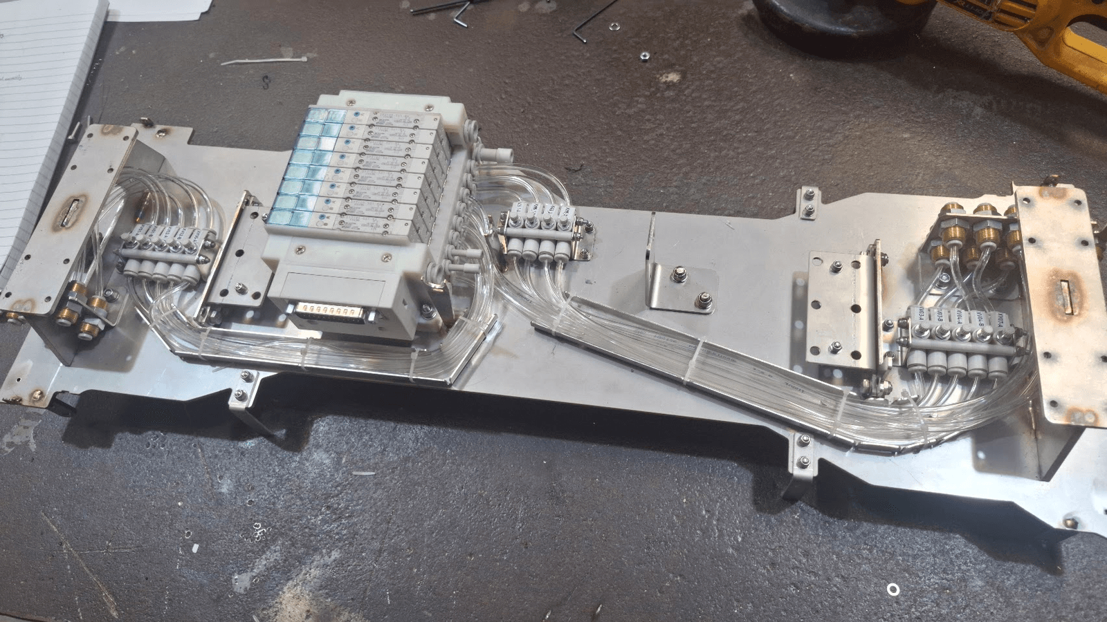
In V1, structure drove component placement. In V1.1, components were placed first and the chassis built around them. That reversal produced defined clearances for moving and serviceable parts, symmetrical load paths, better adjustability, and improved assembly access.
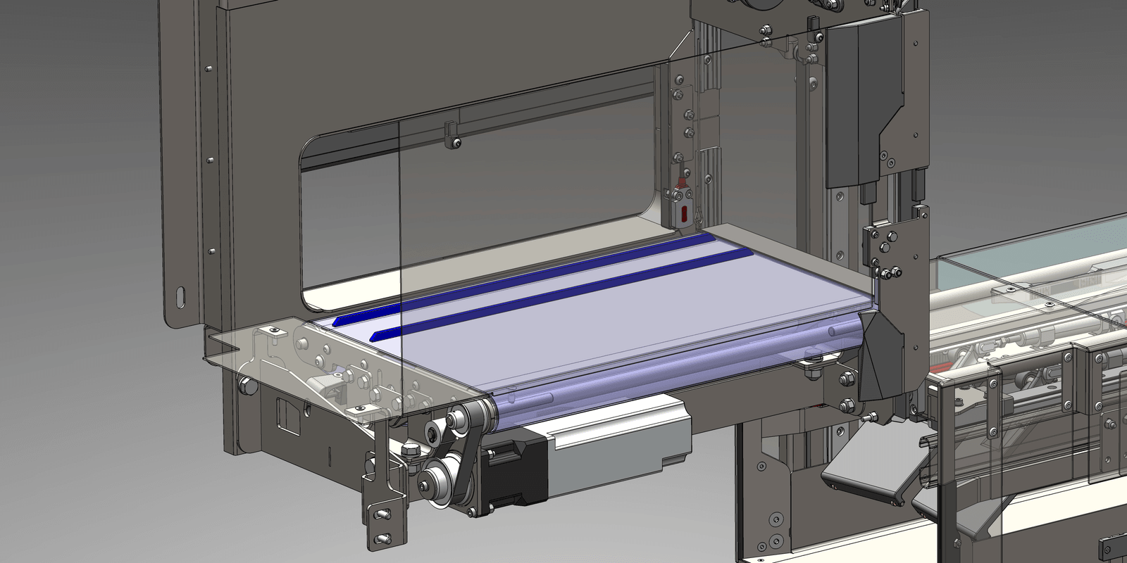
D3Compact conveyor for confined space
A standard conveyor was infeasible in the envelope discovered during prototype testing. Footprint outside the belt face was minimised, the servo relocated beneath the belt where headroom existed, a compact timing belt drive fitted, and adjustability retained for alignment.
D4Building four machines alongside the design
Limited external machine build support meant assembling four complete machines while still designing. The modular sub-assembly hierarchy allowed staggered build across supplier lead times. Fastener selection was driven by tool access and serviceability, not load alone. Slots and adjuster plates absorbed tolerance variation between outsourced and fabricated parts. An improvement log was kept from day one of assembly, and every entry was implemented in V1.1.